39 civil 3d cut and fill labels
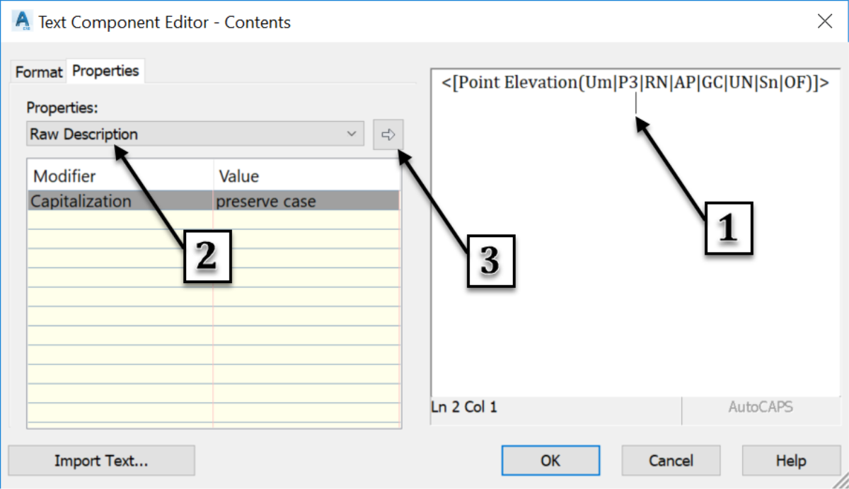
Road design With AutoCAD Civil 3D + Open Chanel Design | Udemy Points label Lecture-3 Alignment creation tools and Settings 1. Draw alignment (no curves) 2. Draw alignment (with curves) 3. Curve settings 4. Insert pi 5. Delete pi 6. Sub-entity editors 7. Pick sub-entity 8. Points editing 9. Alignment grid view Lecture-4 Basic Alignment creation 1. Draw alignment 2. Alignment creation tools 3. Label Styles | Civil 3D 2020 | Autodesk Knowledge Network Create a Surface Spot Elevation label style named "Cut Fill." In the Label Style Composer dialog box, on the Layout tab, change the Name property of the label component to "fill." Change its color to Green. Edit the text component and change the Sign Modifier to Hide Negative Value.
Dynamic Surface Cut-Fill Ticks! FINALLY. - civil4d.com [Note - make sure the color and plot styles are byblock - not bylayer] Modify the label to include two blocks, plus and minus using the size of the two equations above [might want to rename them from minus scale to minus size]. Turn Off the Marker and now you have cut fill ticks, all in color.
Civil 3d cut and fill labels
Expression Driven Cut and Fill Labels | Training Video - cadpilot Kyle demos a classic and basic Civil 3D Cut and Fill Label Style that is modified with Label Style Expressions. Yes. It is also possible to hide the chaff created in this example. This requires a Set of Expressions that work together instead of a pair and the thoughtful use of the Text Component Editor (TCE) component properties. Cut Fill (3D Analyst)—ArcGIS Pro | Documentation Illustration CutFill_3d (Before_Ras, After_Ras, OutRas) When the Cut Fill operation is performed, by default, a specialized renderer is applied to the layer that highlights the locations of cut and of fill. The determinant is in the attribute table of the output raster, which considers positive volume to be where material was cut (removed), and negative volume where material was filled (added). Volme grid map with cut fill labels - Civil 3D & LDD - AutoCAD Forums Civil 3D & LDD ; Volme grid map with cut fill labels Volme grid map with cut fill labels. labels; grid; fill; cut; volume; ... I am trying to create a volume grid map showing cut fill elevation differences at the grid corners and labels in each grid square stating how much cut fill is in that square. I created 2 tin surfaces, Existing Ground ...
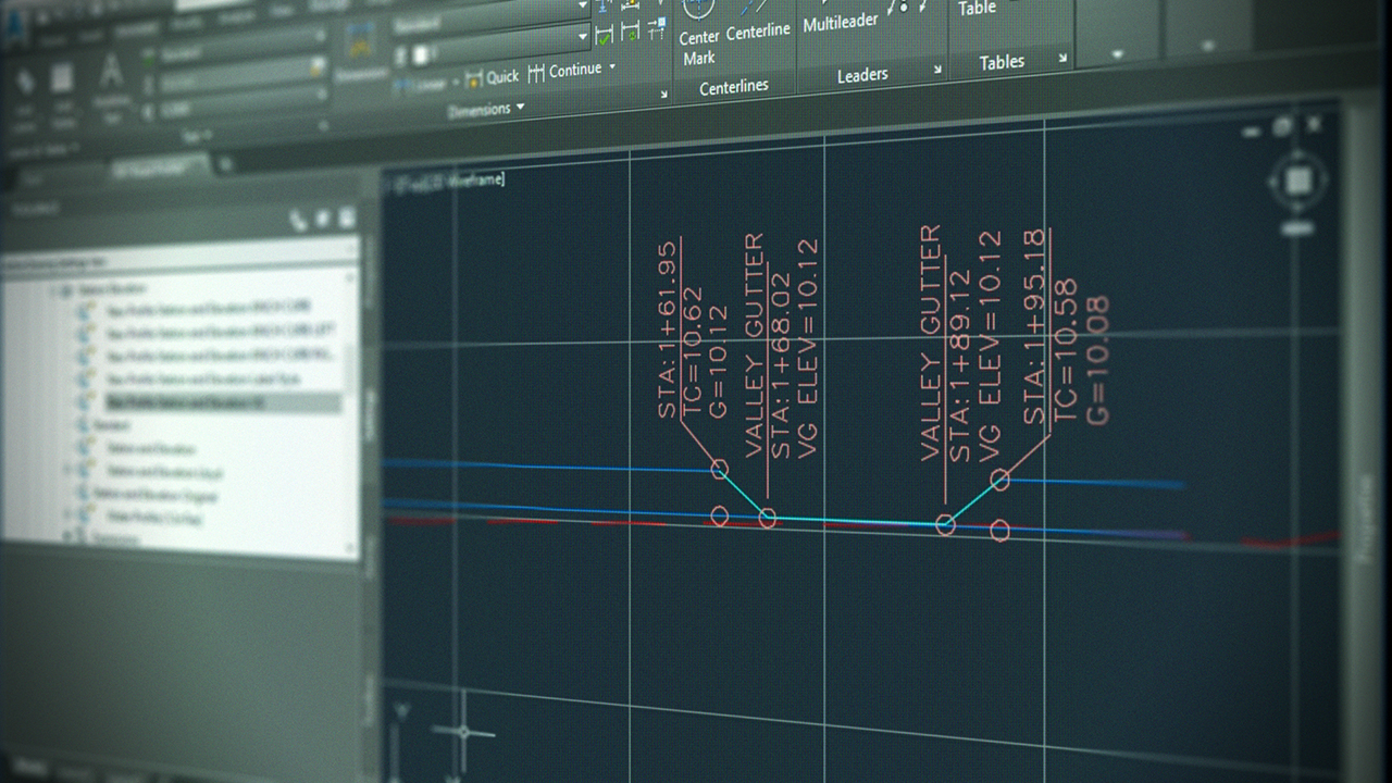
Civil 3d cut and fill labels. Creating Cut/Fill Labels for a Volume Surfaces in Civil 3D Creating Cut/Fill Labels for a Volume Surfaces in Civil 3D - YouTube Learn how to create one Label Style to easily display the cut or fill depth in a Volume Surface by using Label Expressions.-... Express yourself using expressions in Civil 3D - GovDesignHub 5) Create a label style that has 2 components, Cut and Fill text. These components reference the Surface Elevation, but in the text height property, you will set the corresponding expression (Cut/Fill). 6) Change the CUT component color to RED. 7) Change the FILL component to BLUE. 8) Test this out by using your new label style to label a surface!! Band and Code Set Styles (CAD Clinic: Civil 3D Tutorial) - Cadalyst A code set uses code, link, and shape styles to annotate corridor values in a section view. Band Sets. A band set defines what band types and styles appear when applying the set. For example, the band set below uses three band types: surface, horizontal geometry, and superelevation. Each band type has list of styles from which to choose. Cut and Fill volumes - OpenRoads | OpenSite Wiki - Bentley Can I get a quick information about the cut and fill for existing terrain and a surface in OpenRoads? Answer : The "Create Cut and Fill Volumes" tool calculates cut and fill volumes between two surfaces and creates a 3D mesh solid with volume attributes. The volumes can be viewed in "Properties" or "Elemen Information". Steps : 1.
Using Civil 3D to Create a Cut & Fill Earthwork Exhibit Once these areas have been defined, a custom spot elevation label style could be used to identify the amount of cut and fill going on in these areas. The best part is that the colorization and annotations remain dynamic to the model. Any changes made to the design will automatically be reflected in your earthwork visualization. Civil 3D Tip: Adding Section Labels to Section Views - EnvisionCAD 1. Ribbon >> Home tab >> Create Design Panel >> Section Views >> Project Objects To Multiple Section Views 2. Select a section view group. 3. The Project Objects To Multiple Section Views dialog will appear. 4. PDF AutoCAD Civil 3D Tutorials • Each tutorial set contains exercises that are designed to explore the various features of AutoCAD Civil 3D. The tutorial exercises are organized in a logical sequence, based on how you typically work with the different types of features. However, you may complete the exercises in any order you choose. Cut/Fill Color Map - Carlson Software This command creates a cut/fill color map typically in red and blue in order to show the difference between grid or triangulation surfaces. In the options dialog, the ranges of the cut and fill zones are set along with the colors. The Automatic Colors has several colors styles to choose from for the cut to daylight to fill colors.
Solved: cut/fill surface labels - Autodesk Community This method is not really needed as this works well (just been using it today) neilyj (No connection with Autodesk other than using the products in the real world) AEC Collection 2023 UKIE (mainly Civil 3D UKIE and IW) How to change the Alignment and keep our Profile Design - Make it Civil How to join the Profiles. 1. Export the Profiles to Lanxml and then edit the Landxml file and join there the Profiles. Now we could import the new Landxml to AutoCAD Civil 3D. 2. Export the Profiles to an Excel file, then join the Profiles into a new created text file, and then import the new Profile by the command Create Profile from file. AutoCAD Civil 3D Tutorials - Autodesk AutoCAD Civil 3D. The tutorial exercises are organized in a logical sequence, based on how you typically work with the different types of features. However, you may complete the exercises in any order you choose. After you begin an exercise, you should complete the steps in the order presented. Creating Cut/Fill Volume Points or Labels in Civil 3D When you need to show cut and fill values at specific points within Autodesk AutoCAD Civil 3D, first you will need to create a volume surface. Place the desired points (or labels) which have a label style which shows the elevation, using the volume surface as the selection when prompted.
Label Creation for Profiles in Civil 3D | Pluralsight
Plot Long Sections - Civil Survey Solutions First: Select the Civil 3D Profile, Profile Style to apply to the Existing Surface, then pick [OK]. Second: Select the Civil 3D Profile, Profile Style to apply to the Design surface, then pick [OK]. Third: Select the Civil 3D Profile View, Profile View Style to apply for the Long Section, then pick [OK]. Fourth: Select the Civil 3D Profile View, Band Style to apply to the Long Section, then ...

Tutorial: Generating Surface Volume Information
Surface Modeling for Infrastructure Design - Cut and fill ... - Autodesk Open the corridor Properties, and on the Information tab, select Automatic Rebuild. Select the corridor in Prospector, right-click, and choose Rebuild - Automatic. Select the corridor in the drawing, right-click and choose Update Automatically. Select the corridor in the drawing, right-click, and choose Rebuild Automatic.
Creating Civil 3D Label Styles
Civil 3D_Cut & Fill Exhibit Labels - YouTube This video will take the Cut & Fill Exhibit we previously created and show you how to add some extended data labels. We review creating the label so that it references 3 different surfaces and...

Solved: Civil 3D 2012 Point Labels are too big in a Viewport - Autodesk Community
Express Yourself: Using Expressions in Civil 3D - AUGI Create a label style that has two components: Cut and Fill text (see Figure 7). These components reference the Surface Elevation, but in the text height property, you will set the corresponding expression (Cut/Fill). Change the CUT component color to RED. Change the FILL component to BLUE. Figure 7

Contour labels have disappeared in Civil 3D | Govi's Stuff
Solved: Cut Fill Labels on Volume surface - Autodesk Community I have a problem, I need write Cut and Fill Labels on Volume surface in each 10x10 meters. Civil 3D can write Spot Levels on grid, but I need write Cut and Fill values in grid area. Using Surface >Utilities>Bounded volumes I can get the values on selected closed polygon, but write to all is very long work.
AutoCAD Civil 3D 2018 Tip: Use Civil 3D Line Label Styles to Annotate Utility Linetypes ...
Making CUT/FILL Maps in AutoCAD Civil 3D | Part II | ZenTek To begin, let's create the label style we'll need for Cut/Fill mapping. Go to Toolspace > Settings> Surface > Label Styles > Spot Elevation and right-click to create a new style (below). We'll call it CUT-FILL. Next, click on the "Layout" tab and delete the default text entities there.

Civil 3D Reminders: Line Labels
To Create an Earthwork Construction Plan - Autodesk Help The following illustration shows an example of the grid, labels, and tables that are inserted into a drawing when using this command. In the Toolspace, on the Toolbox tab, expand Civil 3D 2016 Productivity Pack 1 Surfaces. Double-click Earthwork Plan Production to display the Create Earthwork Construction Plan dialog box.

Introduction to Civil 3D Part 14 - Parcel Labeling - YouTube
Video: Create Cut Fill Volumes tool - OpenRoads - Bentley It is no longer required to create a terrain model for the proposed rough grade. The objects in the civil model are compared based on the "Volume Option" in the assigned Feature Definition in order to calculate the cut and fill volumes. The video below discusses basic cut and fill volumes using the Existing, Design, Subgrade, and None Volume ...

Freelance Cad Drafting AutoCAD 2D and 3D Drawings Residential Commercial Civil Architectural ...
PDF Cut Fill Spot Labels - amsworkplace.com • Change the Label type to Spot Elevation. • Change the Label Style to the one just created. • Click Add and place several labels to verify the functionality. NOTE: In Civil 3D you must have a TIN volume surface created to properly place Cut and Fill Spot Elevations. Rte 46 West, Bldg.

Civil 3D 2010 - "Creating Custom Linetypes" | Custom, Civilization, Autodesk
Surface Modeling for Infrastructure Design - Creating an existing ... Add surface styles, labels, and tables to convey surface information on your design plans and work with volume surfaces for calculating cut and fill. Finally, wrap up the lesson by creating boundaries for surfaces. After completing this lesson, you'll be able to: Understand surfaces and how they are used in Civil 3D. Build surfaces from project ...

Express yourself using expressions in Civil 3D
Volme grid map with cut fill labels - Civil 3D & LDD - AutoCAD Forums Civil 3D & LDD ; Volme grid map with cut fill labels Volme grid map with cut fill labels. labels; grid; fill; cut; volume; ... I am trying to create a volume grid map showing cut fill elevation differences at the grid corners and labels in each grid square stating how much cut fill is in that square. I created 2 tin surfaces, Existing Ground ...

Cut Fill (3D Analyst)—ArcGIS Pro | Documentation Illustration CutFill_3d (Before_Ras, After_Ras, OutRas) When the Cut Fill operation is performed, by default, a specialized renderer is applied to the layer that highlights the locations of cut and of fill. The determinant is in the attribute table of the output raster, which considers positive volume to be where material was cut (removed), and negative volume where material was filled (added).

Highway Alignment Construction Comparison Using Object-Oriented 3D Visualization Modeling ...
Expression Driven Cut and Fill Labels | Training Video - cadpilot Kyle demos a classic and basic Civil 3D Cut and Fill Label Style that is modified with Label Style Expressions. Yes. It is also possible to hide the chaff created in this example. This requires a Set of Expressions that work together instead of a pair and the thoughtful use of the Text Component Editor (TCE) component properties.

Express yourself using expressions in Civil 3D
Masking Labels in Autodesk Civil 3D - IMAGINiT Civil Solutions Blog

Express yourself using expressions in Civil 3D
Exercise 1: Finding Tools | Civil 3D 2018 | Autodesk Knowledge Network
Post a Comment for "39 civil 3d cut and fill labels"